Bouffalo ISP Protocol V1: Difference between revisions
| (6 intermediate revisions by the same user not shown) | |||
| Line 2: | Line 2: | ||
It is integrated in [[:Category:BL602_Series|BL602]], [[:Category:BL702_Series|BL702]], [[:Category:BL602_Series|BL808]] and [[:Category:BL602_Series|BL616]] series of chips, although, every series have some improvements to this protocol. | It is integrated in [[:Category:BL602_Series|BL602]], [[:Category:BL702_Series|BL702]], [[:Category:BL602_Series|BL808]] and [[:Category:BL602_Series|BL616]] series of chips, although, every series have some improvements to this protocol. | ||
= List of supported interfaces per chip = | |||
List of available interfaces for specific chips: | List of available interfaces for specific chips: | ||
| Line 64: | Line 66: | ||
}} | }} | ||
Currently, there are two ways of getting into ISP mode, which we will describe in | Currently, there are two ways of getting into ISP mode, which we will describe in following sections: | ||
== Via GPIO == | == Via GPIO == | ||
| Line 70: | Line 72: | ||
Every chip using ISP Protocol V1 have ability to get into ISP mode by specifying voltage level on specific pin during boot time. This mechanism is implemented within BootROM code. | Every chip using ISP Protocol V1 have ability to get into ISP mode by specifying voltage level on specific pin during boot time. This mechanism is implemented within BootROM code. | ||
{{Collapse top|title=Example hardware layout}} | BL602 as example, the boot pin needs to be pulled to it's according level (most of times HIGH) 0.1s before powering up the chip via PU_CHIP, and then boot pin needs to be kept at specified level at least 2ms after PU_CHIP get HIGH. | ||
{{Collapse top|title=Example hardware layout|width=unset}} | |||
Example is taken from BL602 Datasheet | Example is taken from BL602 Datasheet | ||
| Line 101: | Line 105: | ||
| IO2 | | IO2 | ||
| High | | High | ||
| | | Multiplexed with JTAG? (not 100% confirmed) | ||
|} | |} | ||
== Via software == | |||
There are registers to reboot the chip and automatically launch ISP mode. (TODO) | |||
= Handshake = | = Handshake = | ||
= Run firmware = | |||
Latest revision as of 06:19, 3 June 2023
This page describes Bouffalo ISP Protocol V1, which is ISP protocol used to run images, write images to Flash or program fuses via UART, USB, SDIO or JTAG.
It is integrated in BL602, BL702, BL808 and BL616 series of chips, although, every series have some improvements to this protocol.
List of supported interfaces per chip
List of available interfaces for specific chips:
| Chip | UART | USB | SDIO | JTAG | SD Card |
|---|---|---|---|---|---|
| BL602 Series | Yes | No | Yes | ? | No |
| BL702 Series | Yes | Yes | No | ? | No |
| BL808C | Yes | Broken | ? | ? | Broken? |
| BL808D | Yes | N/A | ? | ? | N/A |
| BL606P | Yes | ? | ? | ? | N/A |
| BL616 Series | Yes | Yes | ? | ? | ? |
Getting into ISP/BootROM mode
| Currently the BootROM is not explored enough, to know how exactly the boot process works within it, although, we will describe here already known and tested boot flows. |
Currently, there are two ways of getting into ISP mode, which we will describe in following sections:
Via GPIO
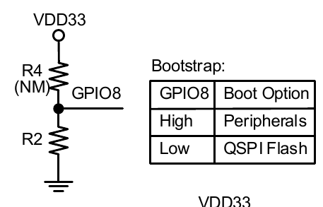
Every chip using ISP Protocol V1 have ability to get into ISP mode by specifying voltage level on specific pin during boot time. This mechanism is implemented within BootROM code.
BL602 as example, the boot pin needs to be pulled to it's according level (most of times HIGH) 0.1s before powering up the chip via PU_CHIP, and then boot pin needs to be kept at specified level at least 2ms after PU_CHIP get HIGH.
| Chip | Pin | ISP Mode when pin is | Note |
|---|---|---|---|
| BL602 Series | IO8 | High | |
| BL702 Series | IO28 | High | |
| BL808 Series | IO39 | High | Multiplexed with QSPI D3 pin |
| BL616 Series | IO2 | High | Multiplexed with JTAG? (not 100% confirmed) |
Via software
There are registers to reboot the chip and automatically launch ISP mode. (TODO)
